Assalamualaikum Everyone. I am @imranhassan
From #Bangladesh
.png)
After opening an old mosquito swatter in my hand, I thought that if I could make a diagram of this circuit myself, then not only would I be able to teach it – but in the future, it would also be possible to teach others or make circuits like my own. From this idea, I designed each part of the circuit in PowerPoint and started to make it a reality one by one.
| 🛠️ Components used in the mosquito swatter circuit and the functions of electronic components |
|---|
Many types of electronic components are used in a circuit. Each has its own function. Below I have given a brief explanation of each important component so that it can be remembered easily:
| 🔸 Diode |
|---|

A diode allows current to flow in only one direction. It is used to prevent reverse current and create DC from AC.
| 🔸 Resistance or Resistor |
|---|

A resistor limits the flow of current. Its function is to control the voltage and current in the circuit.
| 🔸 Capacitor |
|---|

A capacitor holds a charge for a while and releases it when needed. It is used for filtering, preventing fluctuations and conserving energy.
| 🔸 Transistor |
|---|

Transistors work as switches or amplifiers. It helps in converting low voltage to high frequency.
| 🔸 Transformer |
|---|

A transformer works to increase or decrease voltage. It converts low voltage to high voltage, such as is needed to kill mosquitoes.
| Here I have divided the entire circuit into 3 steps: |
|---|
| ✅ Step 1: Getting AC from DC (Battery Charging Circuit) |
|---|

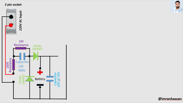
First, I took 220-volt AC input through a 2-pin socket. Then I passed the line through a 100Ω resistor, and then I installed a 1N4007 diode so that there is no reverse current. I filtered it with a 105 capacitor (400V) and a 1M resistor next to it.
Then From here, I installed another diode (1N4007) and sent the charging line to the battery. I also installed a 100µF 25V capacitor so that there is no fluctuation during battery charging.
| ✅ Step 2: Converting the DC voltage of the battery to high voltage (Oscillator & Transformer Circuit) |
|---|

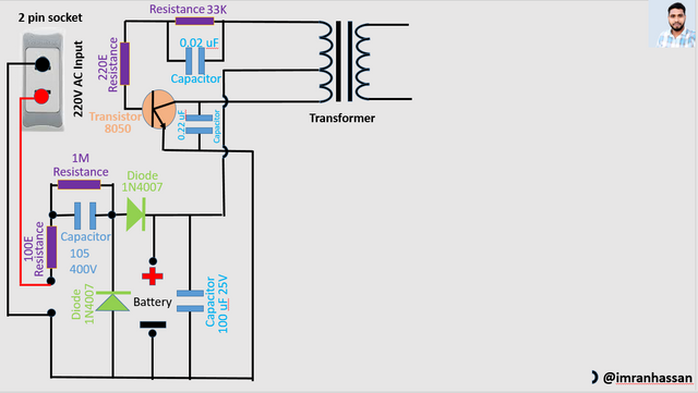
Now I have got the charged power of the battery in DC form. To convert this DC voltage to high voltage, I used an oscillator circuit. Here, a push-pull type internal oscillation has been created using two transistors, a small transformer, some resistors and capacitors. In this, the power coil of the 3.7V battery is changed to a high frequency, which helps the transformer to output high voltage on one side.
| ✅ Step 3: Creating high voltage from the transformer secondary and reaching the mosquito net |
|---|

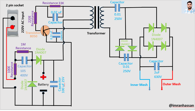
I have installed two 0.01 µF V capacitors from the secondary output of the transformer to filter and stabilise the high voltage signal. Then I have made a bridge rectifier with 4 1N4007 diodes so that the AC signal can be converted to DC. I have further strengthened the high voltage coming out of this rectifier with a 2 µF 630 V capacitor.
Then I have sent this voltage to two meshes – an inner mesh (blue wire) and another outer mesh (red wire). These two meshes are very close to each other. When a mosquito or insect falls between these two meshes, a short circuit is created, and at that moment the insect dies due to a high-voltage shock.
🧰 Components used and their functions
| Component name | Value | Function |
|---|---|---|
| AC input socket | 2 pins | 220V AC supply |
| Resistance (Resistor) | 100Ω | Current limiting and safety |
| Diode (Diode) | 1N4007 (x5) | Ensures one-way current flow (AC → DC) |
| Capacitor (Capacitor) | 105 (400V) | Creates smooth DC by filtering AC |
| Resistance (Bleeder) | 1MΩ | Drains the capacitor's charge quickly |
| Capacitor | 100µF 25V | Keeps the voltage stable during charging |
| Li-ion battery | 3.7V | Stores power and runs the circuit |
| Transistor | 1 pcs | Works as an oscillator, generates frequency |
| Transformer | Small Ferrite Core | Increases voltage (Step-up) |
| High Voltage Capacitor | 0.01µF 250V (x2) | Filters high frequency |
| Bridge Rectifier | 1N4007 Diode (x4) | Converts AC signal to DC |
| Storage Capacitor | 2µF 630V | Holds and releases high voltage |
| Mosquito Net (Mesh) | Two (Inner & Outer) | Destroys insects by applying high voltage |
| Last words: |
|---|

I designed this circuit using PowerPoint and am trying to understand it by actually installing each part one by one. This is a part of my learning, where you can also check your bat's circuit like this if you want.
.gif)
https://x.com/ImranHosen98536/status/1919443807449280885
Downvoting a post can decrease pending rewards and make it less visible. Common reasons:
Submit
PowerPoint? Why didn't you do it in programs like..
https://www.falstad.com/circuit/
https://everycircuit.com/
https://www.tinkercad.com/
Downvoting a post can decrease pending rewards and make it less visible. Common reasons:
Submit
Thank you very much sir for your comment. Sir this is just a diagram. If I want to give this diagram real life then I have to make an animation system and make it like a video.
Downvoting a post can decrease pending rewards and make it less visible. Common reasons:
Submit
Unfortunately, I don't know much about radio electronics, but I'm a little interested. And for beginners, it's better to experiment online. My father was a radio amateur (master), so I'm interested in this myself. But in my time, computers appeared - so I switched all my attention to them
Downvoting a post can decrease pending rewards and make it less visible. Common reasons:
Submit
Thanks for your comment. I'm glad you're interested. Your father's experience as a radio amateur was undoubtedly valuable, and that environment of your childhood was also inspiring. Working with computers is certainly a great place, but if you ever want to get back into electronics, I'll try to encourage you with some simple posts and ideas. Keep your interest - learning never stops.
Downvoting a post can decrease pending rewards and make it less visible. Common reasons:
Submit