Assalamualaikum Everyone. I am @imranhassan
From #Bangladesh

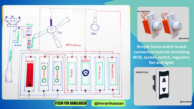
This diagram is helpful in explaining the safe and effective electrical connection of the house. I have drawn this diagram with my own hands so that everyone can understand it easily. Through the previous articles, we have learned how to connect an IPS connection and sub-meter. Through them, you have got an idea about the basic structure of the electrical system in a house or shop.
| Important components of the diagram and a brief description of their work: |
|---|
Utility Pole:

The main source of electricity supply. It brings electricity to the house through the electricity distribution company.
Transformer:

Converts high voltage to low voltage, which is safe for use in the house.
Electric Meter:

Measures the amount of electricity used in the house and helps in determining the bill.
MCB (Miniature Circuit Breaker):

Automatically disconnects power in case of a short circuit or overload in the electrical system.
Indicator Light:

A small lamp or light to show whether the power connection is on or not.
Socket 2 pin:

Where various electrical appliances such as chargers, TVs, refrigerators, etc. are connected.
Switch:

Used to turn electrical devices on or off.
Fan Regulator:

Helps control the speed of the fan - such as low, medium or high.
Fan:

Used to supply air and keep the room cool.
Light

Used to light the house.
| I'm going to start posting my tutorial. Step 1: Connection from Utility Pole to MCB |
|---|

This figure shows the beginning of the electrical connection of a house. Electricity first comes from the Utility Pole and is supplied in a safe state by reducing the voltage through a Transformer.
Then: The connection from the Transformer goes to the Electric Meter, which measures the electricity consumption according to usage. After the meter, an MCB (Miniature Circuit Breaker) is connected to 60 Ampere. It cuts off the power during overload or short circuit, ensuring the safety of the house. This step is very important for the safe power supply of the house.
| Step 2: Connection and component introduction from MCB to Switch Board |
|---|

In this step, the line from MCB enters the Main Switch Board, where various electrical components are located. The components on the board are:
Indicator: This indicates that the line is on and there is power on the board.
Socket : Used to operate various electrical devices such as chargers, rice cookers, etc.
Switch : To turn on/off different lights, fans, etc.
Fan Regulator: Helps to control the speed of the fan.
In this step, the usable power supply of the house is ensured and a safe control system is formed.
| Step 3: Explanation of Indicator, Socket, Switch and Regulator Connection |
|---|

In this step, we will see how to connect various components from MCB, such as – indicator, socket, switch and regulator. First, a wire is brought from the neutral point of the MCB and connected to the neutral point of the indicator. Then the same neutral line is also given to the two sockets. You can see in the figure — the neutral connection is clearly shown in both the sockets. Live (Line) connection from MCB: The live line (red wire) first enters a switch. Then it switches and goes between the two sockets. As a result, these two sockets can be turned on/off through a switch.
| Step 4: Fan Regulator and Switch Connection: |
|---|

On the right side of the board, there is a regulator to control the speed of a fan, a switch to turn on/off the fan, and a switch to turn on/off the light.
First, the live line is connected to the switch (red wire). The connection from the switch goes inside the regulator, then from the regulator it is directly connected inside the fan. Light Switch Connection: The last switch next to the fan is used to turn on/off the light. The live line (red wire) comes to the switch, from there it switches and a line goes directly to the light.
Final Neutral Connection: A line is directly connected from the neutral line of the MCB to the fan and light, so that the circuit is complete.
List of used materials and cost (in Bangladeshi Taka)
| No. | Name of material | Unit price | Number used | Total cost | |
|---|---|---|---|---|---|
| 1 | Meter (Energy Meter) | 1200 | 1 | 1200 | |
| 2 | MCB (2 Pole, 60A) | 550 | 1 | 550 | |
| 3 | Board (8 switch space) | 250 | 1 | 250 | |
| 4 | Indicator Light (Red) | 40 | 1 | 40 | |
| 5 | 2-Pin Socket | 80 | 2 | 160 | |
| 6 | Switch (Standard) | 40 | 3 | 120 | |
| 7 | Regulator (Fan Control) | 180 | 1 | 180 | |
| 8 | Fan (Ceiling Fan) | 2500 | 1 | 2500 | |
| 9 | LED Light (12W) | 300 | 1 | 300 | |
| 10 | Holder/Screw/Tape etc. | 100 | 1 set | 100 | |
| Total cost | 5400 |
.gif)
https://x.com/ImranHosen98536/status/1914961541067379162
Downvoting a post can decrease pending rewards and make it less visible. Common reasons:
Submit
Hi, Greetings, Good to see you Here:)
Downvoting a post can decrease pending rewards and make it less visible. Common reasons:
Submit